Controller Warning and Fault Indications
It is important to have a full understanding of the controller indications to distinguish between normal operating indications and warnings.
.
Reservoir Low Level Warning (After Tolerance Timeout of 10 seconds)
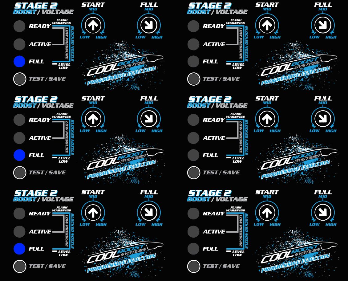
Should the controller receive an open signal from the level monitor, the system will wait 10 seconds before indicating a low-level alarm by continuously flashing the blue LED on the controller face.
The time delay is done to prevent nuisance reporting of low levels on tanks which experience fluid wash.
This condition cannot be cleared or acknowledged by the driver and will only be cancelled when the controller receives a closed signal from the fluid level sensor.
.
Low Pressure Warning *Only when set to 'Status LED'
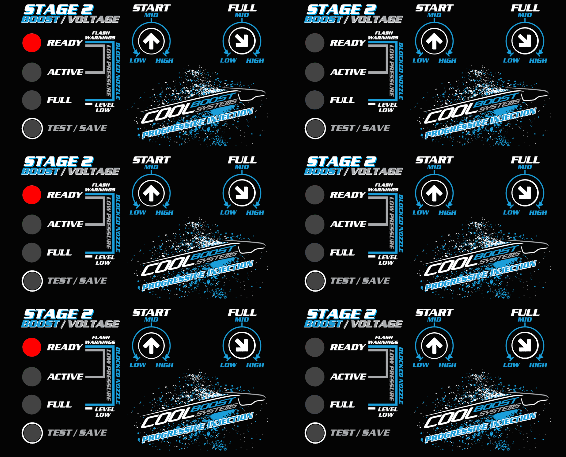
Should your System Pressure Monitoring Unit (SPMU) detect a low pressure during active injection, the controller will indicate this by flashing the Red LED.
This indication will accompany the green or blue LED depending on whether the controller is in progressive ramping or maximum injection control of the pump based on the injection settings.
The controller will not halt injection in this state, this is merely a visual warning to alert the driver of conditional information of the system.
It is recommended that you inspect your system after this detection as it could be related to a blockage, kink, fluid wash, failure of the pump, fuse blow, pipe rupture , solenoid / non return valve failure.
Its recommended that a prime/test be performed and a visual inspection of the system be caried out to identify any issues.
.
Low Pressure Failure *Only when set to 'Boost Safe'

If the system is set to use the boost safe feature and a low pressure is detected, the system will indicate a low pressure warning by flashing the Red LED and shut off system injection after 2 seconds of continuous operation above the pressure checking threshold has passed.
This is done to prevent the possibility of a fire from forming in the engine bay should a line have ruptured and also to prevent damage to the motor if the nozzle is no longer atomizing the fluid effectlvely due to the low pressure.
This condition is indicated via the continuous and simultaneous flashing of the Red and the Green LED's.
In this state, the Auxiliary Output grounds itself (green wires) and if wired correctly to suit, will cause a temporary limp/limitation to protect the motor.
The system will also require driver intervention (acknowledgement) to clear this state which can be done by momentarily pressing the "Test/Save" button for a second.
It is recommended that you inspect your system after this detection as it could be related to a blockage, kink, fluid wash, failure of the pump, fuse blow, pipe rupture , solenoid / non return valve failure.
Its recommended that a prime/test be performed and a visual inspection of the system be caried out to identify any issues.
.
Blocked Nozzle Warning (After Calculated Tolerance Timeout)
If debris blocks the nozzle/s over time/use, the system will begin to retain pressure after activation and take long to depressurize after the non-return /solenoid valve through the nozzle.
This condition will be detected and indicated by the controller if the system takes 25% longer than an average calculation of 3 depressurizations after activation.
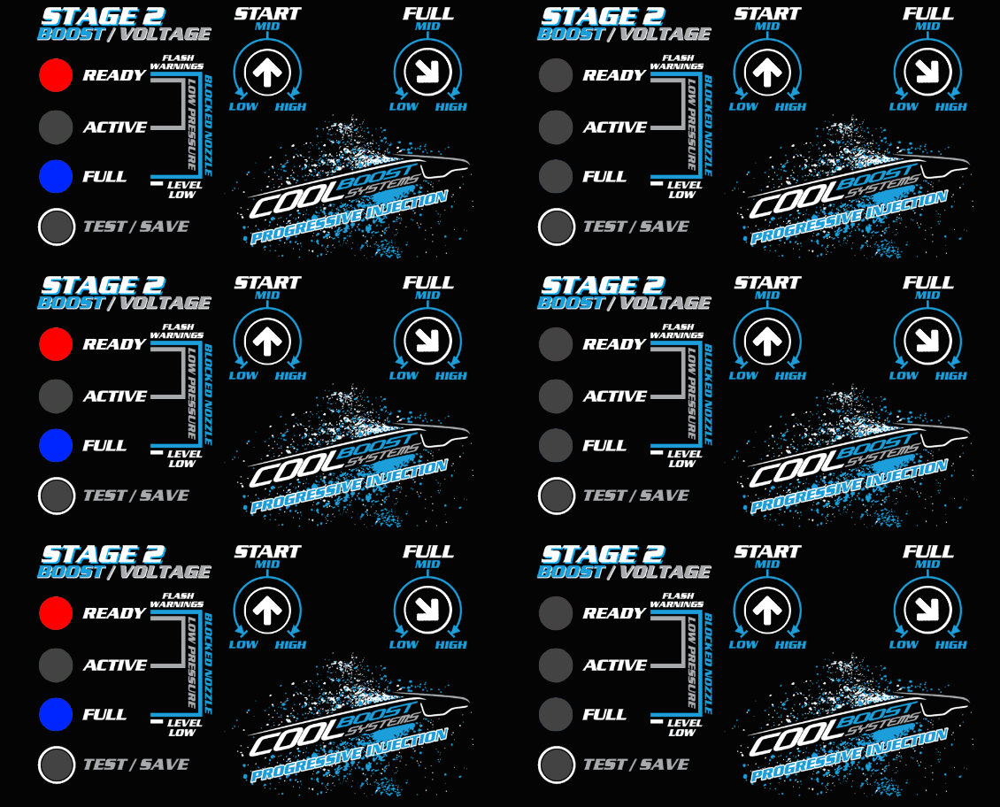
The alarm is identifiable with the simultaneous flashing of the Red and Blue LED's on the controller display and a single flash of the Status LED every second.
This condition does not interlock injection and the system will operate as per normal.
This interlocked state can be reset/acknowledged by momentarily pressing the "Test/Save" button for a second.
It is recommended that you inspect your system after this detection as it could be related to a line crimp, nozzle holder valve failure or nozzle blockage.
Its recommended that the nozzle be removed and be reconnected to the line and a prime/test be performed and a visual inspection of the spray pattern to identify if any issues are present.
.
System Wiring Fault / Controller Failure
Should a critical failure occur internally within the controller or from a wiring issue (such as wiring fault, fuse blow, short to ground or an internal circuit failure), the controller has the ability to detect and prevent this uncontrolled injection which leads to engine hydro-lock.
The controller is designed purposely to handle these types of faults and to isolate its output circuits with its 3 step electrical interlock.
This state will be indicated this with a continuous flashing Red LED which cannot be reset/ acknowledged for as long as the condition is detected.
Its recommended that you contact Cool Boost Support for assistance in this regard and give your system a thorough look over and check the system fuse, wiring and connections.


